Garmin Boat Switch Setup and Wiring Guide
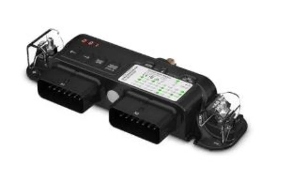
The Boat Switch overview covered what the device does and its 20-channel breakdown. This is the actual install — mounting, power, the NMEA 2000 connection, and the wire-by-wire harness layout, straight from Garmin’s own installation documentation. Garmin explicitly recommends a professional installer for this device, and that’s not boilerplate — between the 50A power feed and the sheer number of harness wires to plan out, this is a bigger job than wiring a single accessory. Treat what follows as what to expect and check, not a substitute for reading Garmin’s full install manual before starting.
Mounting: why “accessible” is a real requirement, not a suggestion
The device needs to mount on a flat, vertical surface with both harness connectors pointing down, somewhere it won’t be submerged, away from strong electromagnetic interference (electric motors, power cables). But the more important requirement is accessibility, for three specific reasons: the hard keys on the unit itself are the fallback for manual switching if the chartplotter connection ever fails, several configuration steps require physically grounding specific wires while standing at the device, and the device uses resettable software fuses that sometimes need a manual reset by pressing buttons directly on the unit. Mounting it somewhere hard to reach defeats all three of those.
Connect to the NMEA 2000 network first
The Boat Switch needs to be on the same NMEA 2000 backbone as the chartplotter you’ll use to control it — same rules covered in the NMEA 2000 setup guide: terminators at both ends of the backbone, T-connectors and drop cables for each device, no daisy-chaining. One detail specific to this device: it does not draw power from the NMEA 2000 bus (Garmin lists it at LEN-0, meaning it doesn’t count against the network’s power budget at all) — it needs its own dedicated 12V power connection separate from the network drop, covered next.
Connect to power: the part with real safety stakes
This is the step Garmin’s manual is most emphatic about. The device needs 6 AWG marine-grade, fully-tinned copper wire rated for 105°C insulation running from a 12V source to the device’s two M6 power terminals, and — this is not optional — that positive feed must run through a 50A circuit breaker or in-line fuse as close to the power source as possible. Skipping the breaker isn’t a “it’ll probably be fine” shortcut; Garmin’s own warning is that a short in an unprotected cable at this gauge and current level is a fire risk. Ring terminals go on both the power and ground wires, secured to the M6 bolts and torqued to 4.5 Nm — not hand-tight, not overtightened enough to risk breaking the terminal bolt.
The same ABYC voltage-drop math that governs every other circuit on the boat applies here too — for longer power runs, size up from the 6 AWG minimum rather than assuming the minimum gauge covers any length of run.
The X1 and X2 harnesses: what’s actually on each wire
The device ships with two pre-terminated wiring harnesses — X1 and X2 — that plug into the module and fan out into individually labeled, color-coded wires. You don’t choose which wire does what; the channels are fixed by the harness, so plan your circuit layout around the existing wire labels rather than trying to remap them.
X1 harness — primary wires:
| Wire label | Color | Gauge | Fuse | Function |
|---|---|---|---|---|
| CH1-TOGGLE 1 (5A) | Gray | 14 AWG | 5A | Nav light output (red/green), tied to CH2 by default |
| CH2-TOGGLE 2 (5A) | Blue | 14 AWG | 5A | Nav/anchor light output, tied to CH1 by default |
| CH3-TOGGLE 3 (5A) | Orange | 14 AWG | 5A | General latching switch |
| CH4-TOGGLE 4 (5A) | Purple | 14 AWG | 5A | General latching switch |
| CH5-TOGGLE 5 (5A) | Green | 14 AWG | 5A | General latching switch |
| CH6-RES TANK 1 | Pink | 16 AWG | — | Resistive tank sender 1 |
| CH7-RES TANK 2 | White | 16 AWG | — | Resistive tank sender 2 |
| CH9-TOGGLE 6 (10A) | Gray/black | 14 AWG | 10A | General latching switch |
| CH10-TOGGLE 7 (10A) | Blue/black | 14 AWG | 10A | General latching switch |
| CH11-LIVEWELL (10A) | Orange/black | 14 AWG | 10A | Livewell pump, auto-cycle timer |
| CH12-BILGE 1 MANUAL (10A) | Brown | 14 AWG | 10A | Manual bilge pump control |
| CH13-BILGE 2 MANUAL (10A) | Brown | 14 AWG | 10A | Manual bilge pump control |
| CH14-BILGE 1 MONITOR | Brown/black | 16 AWG | — | Monitors pump 1’s automatic operation |
| CH15-BILGE 2 MONITOR | Brown/black | 16 AWG | — | Monitors pump 2’s automatic operation |
X2 harness — primary wires:
| Wire label | Color | Gauge | Fuse | Function |
|---|---|---|---|---|
| CH17-DIMMABLE 1 (10A) | Gray | 14 AWG | 10A | Dimmable light output |
| CH18-DIMMABLE 2 (10A) | Blue | 14 AWG | 10A | Dimmable light output |
| CH19-DIMMABLE 3 (10A) | Orange | 14 AWG | 10A | Dimmable light output |
| CH20-DIMMABLE 4 (5A) | Purple | 14 AWG | 5A | Dimmable light output |
| CH21-DIMMABLE 5 (5A) | Green | 14 AWG | 5A | Dimmable light output |
| CH22-VOLT TANK 1 | Pink | 16 AWG | — | Voltage-based tank sender 1 |
| CH23-VOLT TANK 2 | White | 16 AWG | — | Voltage-based tank sender 2 |
| CH25-MOMENTARY 1 (10A) | Gray/black | 14 AWG | 10A | Momentary output (horn, etc.) |
| CH26-MOMENTARY 2 (10A) | Blue/black | 14 AWG | 10A | Momentary output |
| CH27-MOMENTARY 3 (10A) | Orange/black | 14 AWG | 10A | Momentary output |
| CH28-ALWAYS ON (10A) | Purple/black | 14 AWG | 10A | Unswitched constant power |
| CH29-ALWAYS ON (10A) | Green/black | 14 AWG | 10A | Unswitched constant power |
| CH30-START BATTERY SENSE | Yellow/black | 16 AWG | — | Optional start-battery voltage monitor |
| CH32-TANK SENSOR GROUND | Brown/black | 16 AWG | — | Common ground for tank senders and physical bypass switches |
Both harnesses must be connected even if you don’t use every wire — the device expects both plugs seated, and any unused bare wire ends need to be insulated rather than left exposed.
Putting it together: an example wiring plan
The tables above are complete but abstract — here’s what a realistic subset of that wiring looks like mapped to actual devices on a real boat, using the default Option A navigation light wiring:
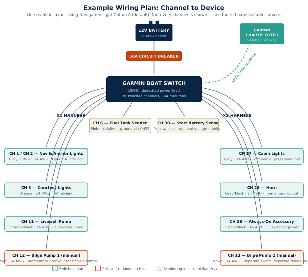
A few things worth noticing in this layout: the two bilge pumps are deliberately split across CH12 (X1) and CH13 (X2) rather than both landing on the same harness — same redundancy logic as the bilge pump buying guide, just applied to which harness carries which pump rather than which battery. The fuel tank sender and start battery sense are monitoring inputs, not switched loads, which is why they don’t draw from the 50A shared budget the way the lighting and pump channels do. And CH12’s breakout wire is the one place in this example plan set up for a physical momentary backup button, since a bilge pump is the channel most worth being able to trigger even if the chartplotter side of the system is having a bad day.
Wiring in a physical backup switch (breakout wires)
Both harnesses also include a second set of thinner 18 AWG “breakout” wires, separate from the primary channel wires above, specifically for adding your own physical remote switch. Each breakout wire corresponds to one specific channel — for example, “SWITCH INPUT: CH12 BILGE 1” on the X2 harness lets you wire a physical button that triggers the bilge 1 pump on CH12 of the X1 harness. To use one, you wire a momentary switch between the breakout wire and the CH32 TANK SENSOR GROUND wire; grounding the breakout wire through the switch triggers that channel.
The rule that matters here, straight from Garmin’s manual: these breakout inputs only work correctly with momentary switches. A latching or toggle switch wired to a breakout input will override the digital switching on that channel and disable chartplotter control of it — it isn’t a supported “wire in a normal switch as backup” path. If the plan is a physical backup button for a bilge pump, livewell, or toggle channel, budget for a momentary push-button switch specifically, not whatever rocker happens to be on hand.
Navigation and anchor light wiring: pick the option that matches your boat
Channels 1-3 have three pre-built interlock configurations to satisfy COLREGS navigation lighting rules, since most boats wire nav lights differently:
Option A (default): one connection for red/green nav lights, one for white nav/anchor lights. Pressing channel 1’s switch toggles both nav lights; channel 2 controls just the anchor light.
Option B: one connection for combined red/green/white nav lights, one for a separate anchor light. Channel 1 controls the combined nav lights, channel 2 controls just the anchor light, and turning one on turns the other off.
Option C: adds a third connection for a steaming light — for boats needing distinct sailing vs. under-power lighting configurations.
Deactivated: channels 1-3 act as three completely independent switches, for boats that don’t need the nav-light interlock behavior at all.
Switching between options is done on the device itself — press and hold switch 1 for 5 seconds until it flashes, then press and hold switch 2 for 5 seconds to cycle to the next option. It’s worth confirming which option actually matches your boat’s nav light wiring before finishing the install, since the default assumes a two-circuit nav light setup that not every boat has.
Configuring the device from the chartplotter
Once everything’s wired and powered, configuration happens from a Garmin chartplotter on the same NMEA 2000 network: Vessel > Switching is the main control screen, and you may need to add a page (Vessel > Switching > Options > Setup > Add Page) to see newly wired channels. The one non-obvious step: every latching, dimming, and momentary channel on this device has to be manually set to “momentary” in the chartplotter’s own switch settings (Options > Settings > My Vessel > Switching > NMEA Standard, select the switch number, Configuration > Momentary) — the Boat Switch device itself decides whether a channel behaves as latching or momentary internally, so the chartplotter just needs to send it a momentary signal rather than trying to manage latching state on its own end. Skipping this step is a common reason a freshly wired channel doesn’t behave correctly even though everything’s connected right.
Tank senders need a separate calibration pass — grounding a dedicated calibration wire on the X2 breakout harness puts the device into calibration mode, then you record min and max fill levels by grounding two more dedicated wires with the tank empty and full. The livewell’s auto-cycle interval (1 to 15 minutes) is adjustable the same way, through its own breakout wire.
Reading the device’s own status lights
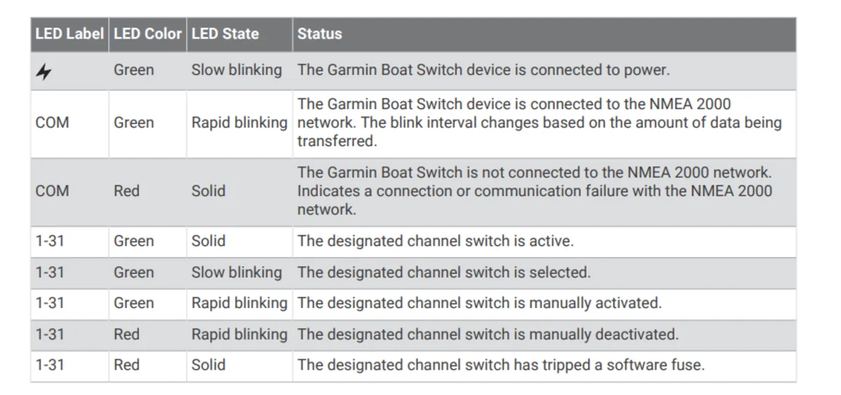
The module has its own status LEDs that are worth knowing before you assume something’s broken: a slow green blink means it’s powered, a rapid green blink on the COM indicator means it’s actively talking on the NMEA 2000 network, and a solid red COM light means it can’t see the network at all — check the backbone connection and terminators first. Per-channel, a solid green LED means that channel is active, a rapid green or red blink means it’s been manually overridden on (green) or off (red) using the device’s own hard keys, and a solid red channel LED means that channel’s software fuse has tripped and needs a manual reset — either from the chartplotter or by holding the RESET/AUTO key on the device for two seconds after selecting that channel.
Bottom line
The mechanical part of this install — mounting, the 50A power feed, the NMEA 2000 hookup — is comparable to any other network device. What makes it a bigger job is the sheer number of harness wires to plan against actual devices before you start, plus the chartplotter-side momentary configuration step that’s easy to miss. Getting the nav light option right for your boat’s actual wiring and using only momentary switches on any physical breakout input are the two details most likely to cause a “why isn’t this working” moment after an otherwise clean install. For everything this device can and can’t do before you buy one, see the Boat Switch overview; for the NMEA 2000 fundamentals this device depends on, see the NMEA 2000 setup guide.
This article may contain affiliate links. If you buy through them, we may earn a small commission at no extra cost to you. Learn more.